SimBio-Vgrid tutorial and examples
Basic example with resolution control
Some simple examples show the basic capabilities of Vgrid.
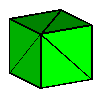
The first sample input image brick2x2x2.v is a uniform brick of 2x2x2 voxels (Fig. 1a).
Such a simple image can be generated by the genimg program in the test directory,
using the command line genimg -n 2 -geom uniform -out brick2x2x2.v.
Using the command lines
| (1a) |
vgrid -in brick2x2x2.v -out mesh1.gmv -format gmv -min 1 -max 1 -elem cube |
| (1b) |
vgrid -in brick2x2x2.v -out mesh2.gmv -format gmv -min 2 -max 2 -elem cube |
| (1c) |
vgrid -in brick2x2x2.v -out mesh3.gmv -format gmv -min 1 -max 1 -elem tetra5 |
| (1d) |
vgrid -in brick2x2x2.v -out mesh3.gmv -format gmv -min 1 -max 2 -elem tetra5 |
gives the following results:
 |
 |
 |
 |
mesh1a.gmv |
mesh1b.gmv |
mesh1c.gmv |
mesh1d.gmv |
The options -in and -out control input and output files.
The -format option controls the output format. Currently we can choose Vista
(default) or gmv (see the GMV homepage).
The option -min gives the minimal cell size (in voxels per direction),
and -max gives the maximal cell size. In the case of one material, we see that only
-max is considered (example 1d).
With -elem, we can choose the cell type, either cube or tetra5.
Several materials and non-uniform meshing
A slightly more interesting example results, when we have two different material.
Let's use a 4x4x4 brick with one corner voxel in a different material (Fig. 2a):
| (2a) |
vgrid -in brick4x4x4.v -out mesh2a.gmv -format gmv -min 1 -max 1 -elem cube |
| (2b) |
vgrid -in brick4x4x4.v -out mesh2b.gmv -format gmv -min 2 -max 2 -elem cube |
| (2c) |
vgrid -in brick4x4x4.v -out mesh2c.gmv -format gmv -min 1 -max 1 -elem tetra5 |
| (2d) |
vgrid -in brick4x4x4.v -out mesh2d.gmv -format gmv -min 1 -max 2 -elem tetra5 |
This gives the following results:
 |
 |
 |
 |
mesh2a.gmv |
mesh2b.gmv |
mesh2c.gmv |
mesh2d.gmv |
In Fig. 2d we can see that choosing -min smaller than -max results in an
non-uniform mesh: The -min controls mesh size at material interfaces,
and -max controls mesh size within a homogeneous material.
Material dependent meshing
Mesh resolution and (in a very limited way) meshing algorithms can be specified on a per-material basis.
This is done via an additional input file specified via the -material option.
Assume we have an input image twomat.v
with 2 labels: 44 and 88 (generated e.g. by genimg -geom two-halves -n 15 -o twomat.v)
Assume our material file two.mat contains the following data:
    material  bg           1   0  0   2  1.0
    material  mat44        4  44 44   1  1.0
    material  mat88        2  88 88   1  1.0
    interface mat44 mat88  1
This means that the material within the label range [44,44]
is called mat44, is to be meshed with resolution 4 voxels,
is to be meshed with the default algorithm (as specified on the command line), and given weight 1.0.
In contrast, the other material corresponding to a voxel value of 88 is meshed with a resolution of 2 voxels,
and the interface of both materials is meshed with a resolution of 1 voxel.
It is always a good idea to explicitely include the background material, as we have done in the first line,
setting the meshing type to none by specifying '2' instead of '1'.
In order to also suppress mesh generation of mat44,
we change the second line of two.mat to
material mat44 4 44 44 2 1.0
and obtain the file one.mat
Neither in one.mat nor in two.mat did we say something about the interface between
background material bg and the other materials.
Then, the interface implicitely is resolved using the finest resolution present of the two materials.
If we do not want any special treatment here,
we can just set the resolution of bg to the highest value occuring in two.mat:
material bg 4 0 0 2 1.0
obtaining bg.mat .
| (3a) |
vgrid -in twomat.v -out mesh3a.gmv -format gmv -min 1 -max 1 -elem cube |
| (3b) |
vgrid -in twomat.v -out mesh3b.gmv -format gmv -material two.mat -elem tetra5 |
| (3c) |
vgrid -in twomat.v -out mesh3c.gmv -format gmv -material one.mat -elem tetra5 |
| (3c) |
vgrid -in twomat.v -out mesh3d.gmv -format gmv -material bg.mat -elem tetra5 |
This gives the following results:
 |
 |
mesh3a.gmv |
mesh3b.gmv Interfaces are refined |
 |
 |
mesh3c.gmv Only one material (mat88) is meshed |
mesh3d.gmv
The interfaces between bg and the other materials are not represented exactly any more |
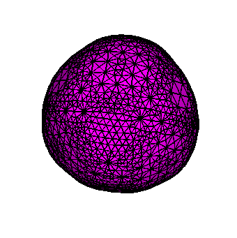
Smooth surfaces with the marching tetrahedra algorithm
The surfaces at material interfaces in the meshes generated so far are axis-parallel.
In general, one would prefer smooth interfaces.
In vgrid, we implement a volumetric variant of the marching tetrahedra algorithm to obtain
tetrahedral meshes with smooth interfaces. This algorithm is activated using the -smooth marching option.
Optionally, the interface can be smoothed iteratively, using the -sm_iters niters option.
This perform niters iterations of Laplacian smoothing.
With the -sm_weights wfile option, a file containing parameters
for Laplacian smoothing can be choosen. If this file is present, Vgrid will cycle
niters times through the parameters in this file.
Having two values like 0.5 and -0.5 in the file
will reduce shrinking (google for "smoothing without shrinking" to learn more).
The major restriction of this implementation is that only one interface is allowed, that is,
only one or two different materials to be meshed.
| (4a) |
vgrid -in ball.v -out mesh4a.gmv -format gmv -min 1 -max 1 -elem cube |
| (4b) |
vgrid -in ball.v -out mesh4b.gmv -format gmv -min 1 -max 1 -smooth marching |
| (4c) |
vgrid -in ball.v -out mesh4c.gmv -format gmv -min 1 -max 1 -smooth marching -sm_iters 30 -sm_weighs laplace.dat |
| (4d) |
vgrid -in ball.v -out mesh4d.gmv -format gmv -min 1 -max 1 -smooth marching -sm_iters 30 -sm_weights symmetric.dat |
where laplace.dat contains 0.5, and
symmetric.dat contains -0.5 0.5.
This gives the following results:
 |
 |
mesh4a.gmv Uniform mesh |
mesh4b.gmv Marching tets |
 |
 |
mesh4c.gmv Marching tets and Laplacian smoothing (30 iterations) |
mesh4d.gmv
Marching tets and symmetric smoothing (30 iterations) |
 |
 |
| Marching tets and Laplacian smoothing (100 iterations) |
Marching tets and symmetric smoothing (100 iterations) |
The shrinkage caused by the Laplacian smoothing is obvious (only the surface mesh is shown).
Excessive boundary smoothing alone would in general decrease the quality of volume elements.
Therefore additional volumetric smoothing (on the interiors nodes) is interleaved with surface smoothing.
By default, a weight of 0.5 is used. A file containing other weights for volume smoothing
can be specified using the
-vsm_weights option.
Note: You should check the quality of the elements after smoothing. Some experimentation
with the parameters may be necessary to obtain the best results. For example, you could add some zeros to the
surface smoothing weights to obtain comparatively stronger volumetric smoothing.